HOW TO ACHIEVE HIGH ULTRASONIC FLOWMETER MEASUREMENT ACCURACY
We’ve all heard the phrase or expression from property experts: “The three most important things about real estate are location, location, location”. Well there is a new twist on that familiar phrase: “The three most important things about flow measurement accuracy are location, location, location”. Unlike other instrumentation (e.g.. temperature, pressure etc.), flow measurement accuracy is very much dependent on the measurement location i.e.. How far the measurement point is placed near any elbow, valve, heat exchanger or other device which modifies the flow profile. This applies to all meters including transit time and USCCFM. So unless your application is simply all straight lengths of pipe (very far away from elbows etc.) the measurement accuracy will be impacted.
Accuracy is particularly important when doing flow measurements in nuclear plants. The nuclear industry is a highly regulated business and must demonstrate traceability to national standards, through various quality assurance programs, analysis, testing and reporting. When ultrasonic meter suppliers quote accuracy numbers, more often than not, they refer to repeatability, and not absolute accuracy. Since our experience is mostly in the nuclear industry, we take this distinction very seriously. This is why USCCFM is the only non-intrusive meter approved by nuclear regulators all over the world. As for most ultrasonic flow meters, USCCFM repeatability depends on the data collection time and for a steady flow can be better than 0.2% if flow readings are taken for 30 minutes or longer . However, absolute accuracy depends on piping configuration. For a long straight pipe, where the flow profile correction factor is known, it is better than 0.5%. For more complicated configurations it will depend on whether laboratory calibration is performed or not. For example, for a single 90 deg elbow between 10 and 20 diameters (L/D) downstream of the elbow, accuracy would be about 1% if no lab calibration was done but can be improved to better than 0.5% with calibrations.
Depending on the flowmeter technology used, it is important to review the flowmeter suppliers recommendations on distances with respect to the measurement point with respect to a flow disturbance both when the point is downstream and in some cases upstream of the disturbance. This is also very important since some technologies are sensitive to the proximity of the measurement point to the downstream flow disturbances. Lab calibration has verified that compared to other technologies the USCCFM is relatively immune to downstream flow disturbances. This can be a distinct advantage in using the USCCFM for existing installations where piping configurations cannot be altered or modified.
The USCCFM meter has been extensively calibrated in accredited flow labs for the most common piping configurations found in a nuclear plant. In order to provide traceability to national standards, normally a gravimetric weighed tank is utilized in accredited labs such as Alden laboratory in the United States, at the National Institute of Standards and Technology, National Research Council (NRC) in Canada and Emerson Laboratory in the Netherlands. All these flow calibration laboratories use a weighing tank to measure the reference flow with better than 0.2% accuracy. This is achieved by measuring the amount of water accumulated in a tank and the time it takes to accumulate it.
A piping configuration to be calibrated is set up and measurements are taken with the meter to be calibrated and compared to the reference flow. An example of an out-of-plane elbow piping configuration testing setup is depicted below.
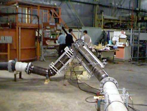
By doing lab calibrations our plant performance engineers have compiled a library of USCCFM flow profile correction factors at various distances (L/D) for common piping configurations such as 90⁰ elbows, reducers, two out-of-plane elbows, T junctions, etc.. However if when using the USCCFM, a measurement location is very close (≤ 5 L/D) downstream of a flow disturbance, laboratory calibration is usually required if high accuracy (< 2%) is needed.
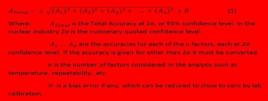
The flow profile correction uncertainty is only one component that needs to be considered when calculating the total measurement error. Assuming that other uncertainty components are random, the total flowmeter accuracy is calculated using the mean Square Root of the Sum of the Squares (SRSS). Such that:
1. USCCFM Reference Accuracy
Volumetric flow measured by the USCCFM is obtained from the following expression:
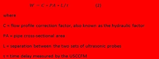
The total uncertainty in W provides the reference accuracy A, as per Eq (1). In other words, A is obtained by taking the mean square root of the sum of squares of individual uncertainties of the terms contributing to W. For the USCCFM each individual uncertainty is discussed below.
1.1 Flow Profile Correction Factor
It has been established in numerous laboratory tests and theoretically that in the case of the fully developed flow the value of the flow profile correction factor for USCCFM is typically a weak function of the Reynolds number and varies over the flow range. For any flow conditions specified and the temperature range, the Reynolds number variation is calculated to determine the variation in the flow profile correction factor such that the uncertainty due to variation in flow conditions such as flow rate, temperature and viscosity are all considered.
The next step is to analyze the piping configurations. For some piping configurations specified, there may be additional uncertainty due to the deviation of the flow profile correction factor from the fully developed value. Reference is made to the compiled library of signatures of flow profile correction factors at various distances (L/D) for common piping configurations found in a nuclear plant. Since a typical uncertainty of laboratory measurements is better than +0.5% and consists of the uncertainty in the reference flow and the USCCFM measurement uncertainty, the total uncertainty for these configurations will be calculated using SRSS or a subset of equation (1).
For other locations, the flow may be very close to fully developed and no additional uncertainty needs to be included.
For locations where no laboratory test results are available, calibration will have to be performed to obtain a reasonably accurate value of the flow profile correction factor. There may be additional uncertainty for this configuration if there is a steep increase in the flow profile correction factor as the flow disturbance is approached.
1.2 Pipe Cross-Sectional Area
Normally, pipe cross-sectional area is calculated based on the OD and wall thickness measurements. Using a traceable micrometer or a pi-tape and a traceable ultrasonic thickness meter, an uncertainty of +0.2% can typically be easily achieved for most pipes. The variation in the wall thickness measurement or the measured ID and OD must be considered. If no additional thickness measurements are done at the specific measurement locations, the uncertainty in the inner diameter can be determined from its total variation. This value is typically equal to 3σ, or 99% confidence level and has to be converted to the 2σ , or 95% confidence level value which gives the uncertainty in the cross-sectional area. If a liner is included in the piping it must also be considered.
1.3 Probe Separation
USCCFM has four or more probes which produce two or more ultrasonic beams propagating across the pipe. The measured time delay is directly proportional to the separation between the probes. The frame holding the probes is manufactured to high tolerances, and the uncertainty in the probe separation is typically better than +0.005”, or for a typical 12” separation, gives the uncertainty of less than 0.1%
1.4 Measured Time Delay
The uncertainty in the measured time delay is determined by the following three contributions:
a) repeatability in the measured time delay
b) reproducibility due to transducer installation
c) possible bias introduced by the meter circuitry
Typical values of these contributions are summarized below.
A one σ scatter in the collected points typically varies between 1% and 2%, and a typical data collection period is one point every 4 seconds. Therefore, 450 points will be collected over a 30 minute collection period, which gives the 2σ uncertainty in the average time delay over the collection period of
 This value can be further reduced by extending the data collection period.
Transducer installation is done according to a well-defined procedure. However, the resulting beam alignment could have an effect on the measured time delay. A number of laboratory tests have confirmed that repeatability due to transducer installation is better than +0.2%.
Time delay bias in the USCCFM electronic circuitry is periodically verified against a traceable calibrator based on a very stable quartz clock. Circuitry is not adjusted if the resulting time delay is different from the calibrator by less than 0.05 ms. For a typical measured time delay of between 50 ms and 100 ms this results in values from 0.05% and 0.1%.
The total uncertainty in the measured time delay is therefore about +0.3 %
1.5 Total Reference Accuracy
The total reference accuracy is then determined by combining individual contributions into equation (1)
Other contributions are considered and discussed below:
1.6 Drift Uncertainty
The only source of the drift uncertainty is possible drift in the electronic circuitry. If verification against the traceable calibrator is done as per specification, there will be no additional contribution from the drift uncertainty as it has been included in 1.4 above.
1.7 Measuring and Test Equipment Uncertainty
This contribution has been included in the flow profile correction factor uncertainty when its value is obtained using laboratory calibration discussed in 1.1 above.
1.8 Setting Tolerances
The use of the traceable calibrator discussed in 1.4 above is done using a well defined procedure and no additional inaccuracy is introduced in the process.
1.9 Power Supply Effects
Since maximum allowed deviation of the time delay from the value provided by the traceable calibrator discussed in 1.4 above includes all potential sources of the drift in the electronic circuitry, changes in the voltage supplied to the USCCFM has no additional effect on the instrument accuracy.
1.10 Temperature Effects
There are two possible effects of ambient temperature on the instrument accuracy. The first effect is on the electronic circuitry, which is included in 1.4 above. The second effect is through the thermal expansion of the pipe and of the transducer frame. Any fluid temperature variation and ambient air temperature variations are considered. Assuming, conservatively, that variation in pipe temperature is the same as the ambient air temperature, and using coefficient of thermal expansion for the pipe material, results in a calculation of the pipe area variation. The same assumption for the aluminum transducer frame with the coefficient of thermal expansion of 23*10-6 per degree Celsius, results in calculating changes in the probe spacing
1.11 Humidity, Radiation, Seismic, Static Pressure Effects and Readability
These factors typically have no effect on the instrument uncertainty either because of the typical assumptions specified for the application or because of the non-intrusive, digital nature of the USCCFM.
2.0 Total USCCFM Accuracy
Combining the uncertainty contributions listed above allows for the calculation of the total reference accuracy. For other cases, where the total uncertainty may be higher than the specified design accuracy, it can always be bounded by about 1% if lab calibration is performed. It should be noted that uncertainties quoted for some of the terms are based on our experience with USCCFM in a variety of applications at temperatures from 40ºF to 450ºF and pipe diameters from 1” to 36”. Actual uncertainty values for the installations on the measurement locations should be calculated based on the data collected and on laboratory calibration work that has to be performed.
WH Technologies assumes no liability for any information contained or used in this application note.